Adaptive points are points in 3D space that are created by modifying reference points. The geometry
drawn by snapping to these flexible points results in an adaptive
component.
Adaptive components can be used in pattern panel families,
adaptive component families, conceptual massing environment, and
projects. were introduced in the 2011 release of Revit. They are an adaption of the pattern based curtain
panel. Adaptive families, unlike a standard parametric family, which can
be resized by flexing and changing values are able to adapt to
different situations and scenarios in a building, controlled by the
points you setup. They are often used for panels and curtain panels
which are similar in appearance and function but different sizes.
*Adaptive families are able to ‘adapt’ to their surrounding by settings
points as markers or connectors.( e.g. A square panel will have 4
adaptive points which you will add on each of the 4 corners of the
structural framing.)
Just how complex Revit works, there are a number of different complexities
to adaptive families, they can be used for simple geometry for instance
piping or beams all the way up to advanced modeling techniques, such as
rotating panels requiring an excellent work station to be able to
handle the detail and repetition on a large scale and utilizing Dynamo plug-in.
In this post I will try and get a full understanding of what a Adaptive Point is, how Adaptive Components relate nto each other and how they act once loaded into Revit's project file then once I've broke down the understandings of its workings we jump to Dynamo!!!
Before jumping in to creating an adaptive family, it is worth taking
some time out to plan how your family is going to function. With normal
generic families, we lay out reference planes to constrain our geometry,
with adaptive panels I like to use reference planes in a grid format
and repeat the same grid in the Revit project when adding the family.
*This consistency will reduce the chances of errors etc when you are
loading your family.
When starting a adaptive family try and consider the following:
- Add your ‘Point Elements’ in the same order that you want to insert your geometry into your project.
- Don't forget to set out grids if you are working on more than one level.
- Adaptive points have their own X and Y reference planes attached,
when working with solid forms, use these planes to constrain the points
to the geometry.
- Be sure to use ‘Reference Lines’ rather than ‘Model Lines’ when referencing your point to the form.
- Flexibility is KEY so go ahead and test your points are acting and reacting the way you expect, in the same way you’d flex a standard Revit family.
Step One: Adaptive Points/Components/Families Creation
Start a new family with an adaptive template.

> Open > Family > Browse/Selected the “Adaptive Generic
Model Family” template on you machine. This opens a new blank template with and X and Y
reference plane.
Add/Place Reference Planes and Point Elements(See Image below for reference)*
Keep a consistency
with the spacing between planes, this is important when bringing the
family into your project.
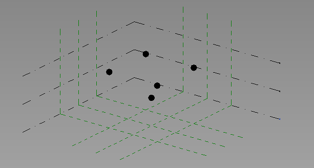
Use the view cube to lay out your points, you may notice that your
points aren’t snapping to the reference planes unless you are in a
‘top’, ‘left’ or ‘right’ view. As mentioned above, make sure to enter
your points in the same sequence you will add them into your project.
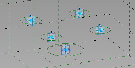
Once you are happy with the location of your points, highlight them all
and click the ‘Make Adaptive’ icon on the ‘Adaptive Component’ tab. In
this instance, I am going to create a random form, just to illustrate
how adaptive points work.
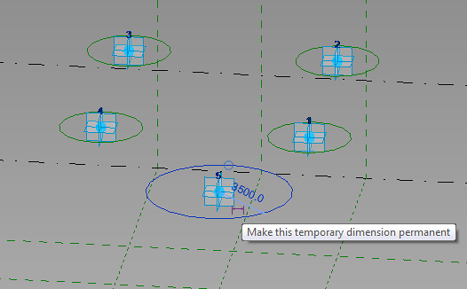
Use the ‘Set’ tool in the work plane tab, and go through each
adaptive point one by one and select the horizontral face as shown on
point 5 above. Once we are working on the correct plane, we can begin to
create the starting point for our geometry. When creating these circles
as shown above make sure to use ‘Reference Lines’ rather than model
lines. Solid forms and masses can be constrained and controlled by
reference lines but not model lines. We now want to add some parameters
to our reference circles. To do this, simply highlight the reference
circle, and click the ‘Make this temporary dimension permanent’ icon as
shown below.
Once we have made all of our reference lines into permanent
dimensions, we are able to add a parameter to control the size of the
circles. Simply add a type parameter in the way you would with a normal
family. Select the dimension, click on the ‘Add label’ dropdown in the
actions bar and a parameter name related to the object. I will use
‘Bottom Width’ for point 5 and ‘Top Width’ for points 1-4 as they will
all be the same size. You will now see these parameters appear in the
‘Family Types’ dialogue where you will be able to control the dimensions
and add formulas etc. Set your reference lines to the correct sizes and
we are almost ready to start adding some geometry. It is a good idea to
test your new parameters and move your adaptive points around to check
that everything is behaving correctly.
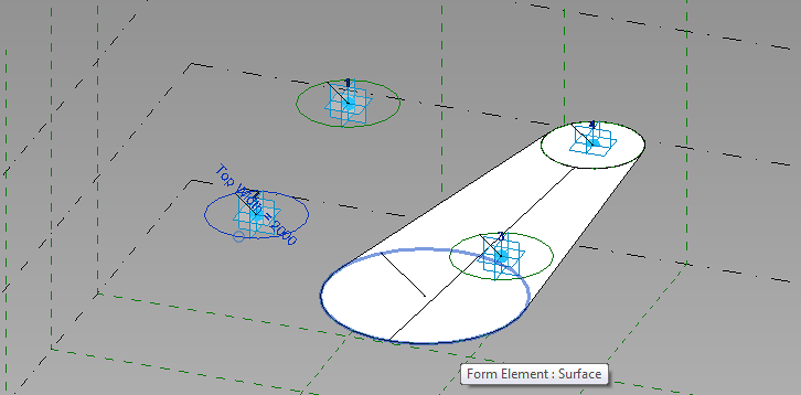
We now want to add some solid geometry to our adaptive points. There
are of course a number of different ways to do this depending on the
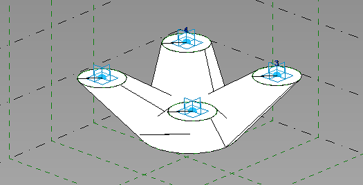
desired result. Here I will be selecting point 1-5, 2-5, 3-5, 4-5.
Select reference line 1 and while holding down control, tab through your
elements until you are selecting reference line with adaptive point 5
in. Select both of these and then hit ‘Create Form’ in the ‘Form’ tab on
the ribbon. Repeat this step until you have 4 ‘spokes’ coming out of
the wider base. If you have followed the same instructions that I have
given, your adaptive family will look like the image below.
Again you should now move around your adaptive points and test your
parameters to check that they are performing the way they should be.
Once you have completed this you are ready to save your family and add
it in to a revit project. Test it out by connecting it to a Mass. It is a
simple procedure and only requires you to add the points in the same
way that you have added them in your family. I sometimes find it easier
to recreate the grids in a mass environment in the Revit project. You
can also switch nodes on to your grid lines to make the placing of
points simpler.
If you have any problems or questions, leave me a comment and I’ll get back to you as soon as possible.


